- Multiplexer/Demultiplexer
This POST is about electronic switching. For telecommunications, see multiplexing

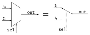
- In electronics, a multiplexer (or MUX) is a device that selects one of several analog or digital input signals and forwards the selected input into a single line. A multiplexer of 2n inputs has n select lines, which are used to select which input line to send to the output. Multiplexers are mainly used to increase the amount of data that can be sent over the network within a certain amount of time and bandwidth. A multiplexer is also called a data selector.Schematic of a 2-to-1 Multiplexer. It can be equated to a controlled switch.2.
An electronic multiplexer makes it possible for several signals to share one device or resource, for example one A/D converter or one communication line, instead of having one device per input signal.
Conversely, a demultiplexer (or demux) is a device taking a single input signal and selecting one of many data-output-lines, which is connected to the single input. A multiplexer is often used with a complementary demultiplexer on the receiving end.
An electronic multiplexer can be considered as a multiple-input, single-output switch, and a demultiplexer as a single-input, multiple-output switch. The schematic symbol for a multiplexer is an isosceles trapezoid with the longer parallel side containing the input pins and the short parallel side containing the output pin. The schematic on the right shows a 2-to-1 multiplexer on the left and an equivalent switch on the right. The wire connects the desired input to the output.
by:maryam jamilah bt abdullah


0 comments:
Post a Comment