DECODER


  • Decoder/Encoder


      A decoder is a device which does the reverse operation of an encoder, undoing the encoding so that the original information can be retrieved. The same method used to encode is usually just reversed in order to decode. It is a combinational circuit that converts binary information from n input lines to a maximum of 2n unique output lines.
In digital electronics, a decoder can take the form of a multiple-input, multiple-output logic circuit that converts coded inputs into coded outputs, where the input and output codes are different. e.g. n-to-2n, binary-coded decimal decoders. Enable inputs must be on for the decoder to function, otherwise its outputs assume a single "disabled" output code word. Decoding is necessary in applications such as data multiplexing, 7 segment display and memory address decoding.


           An encoder is a device, circuit, transducer, software program, algorithm or person that converts information from one format or code to another, for the purposes of standardization, speed, secrecy, security, or saving space by shrinking size.


by:maryam jamilah bt abdullah

MULTIPLEXER


  • Multiplexer/Demultiplexer

This POST is about electronic switching. For telecommunications, see multiplexing
.

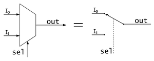
  1. Schematic of a 2-to-1 Multiplexer. It can be equated to a controlled switch.


    2.

    Schematic of a 1-to-2 Demultiplexer. 
    Like a multiplexer, it can be equated to a controlled switch.
    In electronics, a multiplexer (or MUX) is a device that selects one of several analog or digital input signals and forwards the selected input into a single line. A multiplexer of    2n inputs has n select lines, which are used to select which input line to send to the output. Multiplexers are mainly used to increase the amount of data that can be sent over the network within a certain amount of time and bandwidth. A multiplexer is also called a data selector.
    An electronic multiplexer makes it possible for several signals to share one device or resource, for example one A/D converter or one communication line, instead of having one device per input signal.
    Conversely, a demultiplexer (or demux) is a device taking a single input signal and selecting one of many data-output-lines, which is connected to the single input. A multiplexer is often used with a complementary demultiplexer on the receiving end.
    An electronic multiplexer can be considered as a multiple-input, single-output switch, and a demultiplexer as a single-input, multiple-output switch. The schematic symbol for a multiplexer is an isosceles trapezoid with the longer parallel side containing the input pins and the short parallel side containing the output pin. The schematic on the right shows a 2-to-1 multiplexer on the left and an equivalent switch on the right. The wire connects the desired input to the output.

by:maryam jamilah bt abdullah

PARALLEL PROCESSOR


  • what is parallel computing?
  1. Traditionally, software has been written for serial computation:
  2. To be run on a single computer having a single Central Processing Unit (CPU);
  3. A problem is broken into a discrete series of instructions.Instructions are executed one after another.
  4. Only one instruction may execute at any moment in time.


Serial computing

for example:

Serial computing
  • parallel computing is the simultaneous use of multiple compute resources to solve a computational problem:      

  1. To be run using multiple CPUs
  2. A problem is broken into discrete parts that can be solved concurrently
  3. Each part is further broken down to a series of instructions
  4. Instructions from each part execute simultaneously on different CPUs


Parallel computing
for example:

Parallel computing

  • The compute resources might be:

  1. A single computer with multiple processors;
  2. An arbitrary number of computers connected by a network
  3. A combination of both.

  • The computational problem should be able to:

  1. Be broken apart into discrete pieces of work that can be solved simultaneously;
  2. Execute multiple program instructions at any moment in time;
  3. Be solved in less time with multiple compute resources than with a single compute resource.
by:maryam jamilah bt abdullah


PROCESSOR


by:maryam jamilah bt abdullah
  • Defination of CPU

 A CPU is a central processing unit, the core of a computer's functionality. The CPU is  the main part of a computer that processes the mathematical calculations necessary for a computer's functions. CPUs are commonly called the "brains" of a computer because it cannot function without its CPU component.


  • Two components of CPU
  1. the arithmetic logic unit (ALU)
  2. control unit (CU)          


  • Function of CPU   


  1. -CPUs are designed to execute a program's instructions. 
  2. -Programs are stored as number sequences in the computer's memory.
  3. -CPUs carry out programming instructions in the same format as the original stored-program computer developed by John von Newmann.
  4. -The instructions are executed in four steps -- fetch, decode, execute and writeback. CPUs fetch by getting the program's instructions, then the instructions are decoded. As the CPU decodes the instruction, it sorts and prioritizes the program's information in preparation for execution.
  5. -Execution is where the CPU completes the program's instructions. Upon completion of a program's execution, the CPU writes back the execution results so that it is stored in its internal register or computer memory. When the program is accessed again, the CPU may access the program's write-back information.
  • Type of CPU  (most popular) 
  1.   INTEL         
  2.   AMD CPUs  

MIPS Assembly


By : ATHIRAH BT ZAHARUDIN

MIPS Assembly Arithmetics Instruction

All arithmetic and logical instructions have 3 operands
Operand order is fixed (destination first):
       <opcode>   <dest>, <src1>, <src2>

Example:

       C code:      a = b + c;
   
      MIPS ‘code’: add a, b, c

“The natural number of operands for an operation like addition is three…requiring every 
instruction to have exactly three operands, no more and no less, conforms to the 
philosophy of keeping the hardware simple”


Assembly Arithmetic Instructions


Design Principle:  simplicity favors regularity.


Of course this complicates some things...
                 
                 C code:                              a = b + c + d;
                 MIPS pseudo-code:              add a, b, c
                                                          add a, a, d
Operands must be registers (or immediates), only 32 registers are provided 
Design Principle:  smaller is faster.


addi
addiu
addu
div
mult
multu
sub
subu
...


Immediates

In MIPS assembly, immediates are literal constants.

Many instructions allow immediates to be used as parameters.
                            addi $t0, $t1, 42  # note the opcode
                            li $t0, 42       # actually a pseudo-instruction

Note that immediates cannot be used with all MIPS assembly instructions; refer to your 
MIPS reference card.

Immediates may also be expressed in hexadecimal:  0xFFFFFFFF


MIPS Assembly Logical Instructions

Logical instructions also have 3 operands:
    <opcode>   <dest>, <src1>, <src2>

Examples:
            and $s0, $s1, $s2   # bitwise AND
            andi $s0, $s1, 42
            or  $s0, $s1, $s2   # bitwise OR
            or  $s0, $s1, $s2   # bitwise OR
            ori $s0, $s1, 42
            nor $s0, $s1, $s2   # bitwise NOR (i.e., NOT OR)
            sll $s0, $s1, 10      # logical shift left
            srl $s0, $s1, 10     # logical shift right

QTP: MIPS assembly doesn’t include the logical operation not. 


Assembly Load and Store Instructions


Transfer data between memory and registers

 Example:

             C code:        A[12] = h + A[8];
             MIPS code:    lw $t0, 32($s3)   # load word
                                add $t0, $s2, $t0
                                sw $t0, 48($s3)   # store word

Can refer to registers by name (e.g., $s2, $t2) instead of number
Load command specifies destination first: opcode <dest>, <address>
Store command specifies destination last: opcode <dest>, <address>

Remember arithmetic operands are registers or immediates, not memory!
Can’t write:   add 48($s3), $s2, 32($s3)


Addressing Modes


In register mode the address is simply the value in a register:
lw $t0, ($s3)

In immediate mode the address is simply an immediate value in the instruction:
lw $t0, 0

In base + register mode the address is the sum of an immediate and the value in a 
register:
          lw $t0, 100($s3)

There are also various label modes:
                                                    j absval
                                                    j absval + 100
                                                j absval + 100($s3)


Calculation


MIPS
- loading words but addressing bytes
- arithmetic on registers only

# Instruction              # Meaning
add $s1, $s2, $s3        #  $s1 = $s2 + $s3
sub $s1, $s2, $s3        #  $s1 = $s2 – $s3
lw $s1, 100($s2)        #  $s1 = Memory[$s2+100]
sw $s1, 100($s2)        #  Memory[$s2+100] = $s1


HERE IS THE MIPS REFERENCE DATA


Below is the CPU Arithmetics Instruction


ADD      Add Word
ADDI     Add Immediate Word
ADDIU   Add Immediate Unsigned Word
ADDU    Add Unsigned Word
CLO      Count Leading Ones in Word
CLZ      Count Leading Zeros in Word
DIV       Divide Word
DIVU     Divide Unsigned Word
MADD   Multiply and Add Word to Hi, Lo
MADDU Multiply and Add Unsigned Word to Hi, Lo
MSUB    Multiply and Subtract Word to Hi, Lo
MSUBU  Multiply and Subtract Unsigned Word to Hi, Lo
MUL     Multiply Word to GPR
MULT   Multiply Word
MULTU Multiply Unsigned Word
SEB     Sign Extend Byte
SEH     Sign Extend Halfword
SLT     Set on Less Than
SLTI    Set on Less Than Immediate
SLTIU  Set on Less Than Immediate Unsigned
SLTU   Set on Less Than Unsigned
SUB     Subtract Word
SUBU   Subtract Unsigned Word


MIPS INSTRUCTION SET


Operation on Integers

by: Maryam Jamilah bt Abdullah.

                >BINARY ADDITION                                           

  • ~       The four basic rules for binary addition are:


    1.      0 + 0 = 0           Sum of 0 with carry of 0

    2.      0 + 1 = 1           Sum of 1 with carry of 0

    3.      1 + 0 = 1           Sum of 1 with carry of 0

    4.      1 + 1 = 10           Sum of 0 with carry of 1

    Example:10+10=100            
                                                    1  0
                                          +        1  0
                                          __________
                                                1  0  0


          10 + 10 = 100, because  in the basic rule 0+0=0 and 1+1=10. Since 1 is largest digit in the binary system , any sum is greater that  1 requires a digit to be carried over. 


                                           >BINARY SUBTRACTION

    ·    The four basis rules for binary subtraction are:
    1.     0 - 0 = 0
    2.     1 - 1 = 0
    3.     1 -0  = 1
    4.     10 - 1 = 1            0-1 with a borrow of 1   
    ·     A borrow is required in binary subtraction only when we need to subtract a 1 from a 0 

    EXAMPLE:
    a)11-10
    b)101-011

    SOLUTION:
    a)       
                   1        1
    -       1         0
                0          1

    b)

                    1 0      2       1

         -    0         1          1
               0      0          1

    •    Left column: When a 1 is borrowed, a 0 is left , so 0 – 0 = 0
    •    Middle column: Borrow 1 from  left  column , making 2  which   mean 10 in  binary,when 2 borrowed it become 1, then 1-   1=0        
    • Right column: Borrow 1 from middle column , making 10then  10- 1=1  

          >BINARY MULTIPLICATION


    Multiplication in binary is similar to its decimal counterpart. Two numbers A and B can be multiplied by partial products: for each digit in B, the product of that digit in A is calculated and written on a new line, shifted leftward so that its rightmost digit lines up with the digit in B that was used. The sum of all these partial products gives the final result.

    Since there are only two digits in binary, there are only two possible outcomes of each partial multiplication:
    • If the digit in B is 0, the partial product is also 0
    • If the digit in B is 1, the partial product is equal to A
    For example, the binary numbers 1011 and 1010 are multiplied as follows:
               1 0 1 1   (A)
             × 1 0 1 0   (B)
             ---------
               0 0 0 0   ← Corresponds to a zero in B
       +     1 0 1 1     ← Corresponds to a one in B
       +   0 0 0 0
       + 1 0 1 1
       ---------------
       = 1 1 0 1 1 1 0

    >BINARY DIVISION


    Binary division is again similar to its decimal counterpart:
    Here, the divisor is 1012, or 5 decimal, while the dividend is 110112, or 27 decimal. The procedure is the same as that of decimal long division; here, the divisor 1012 goes into the first three digits 1102 of the dividend one time, so a "1" is written on the top line. This result is multiplied by the divisor, and subtracted from the first three digits of the dividend; the next digit (a "1") is included to obtain a new three-digit sequence:
                  
                 __1_________
    1 0 1   ) 1 1 0 1 1 
            −   1 0 1
                 -----
                0 1 1


Function Of I/O Modules

By : ATHIRAH BT ZAHARUDIN

The Function Are :

1)   Control and Timing.
2)   CPU Communicating.
3)   Device Communication.
4)   Data Buffering.
5)   Error Detection.


1)   Control and Timing
  •     Required because of multiple devices all communicating on the same channel
  •         Example :-

–CPU checks I/O module device status
–I/O module returns status
–If ready, CPU requests data transfer
–I/O module gets data from device
–I/O module transfers data to CPU
–Variations for output, DMA, etc.


2)   CPU Communicating

  •      Commands from processor – Examples: READ SECTOR, WRITE SECTOR, SEEK track number, and SCAN record ID.
  •        Data – passed back and forth over the data bus
  •        Status reporting – Request from the processor for the I/O Module's status.  May be as simple as BUSY and READY
  •        Address recognition – I/O device is setup as a block of one or more addresses unique to itself


3)   Device Communication.
  •    Specific to each device
4)   Data Buffering.
  •    Due to the differences in speed (device is usually orders of magnitude slower) the I/O module needs to buffer data to keep from tying up the CPU's bus with slow reads or writes
5)   Error Detection.

  •        simply distributing the need for watching for errors to the module They may   include:
               - Malfunctions by device (paper jam)              

                      - Data errors (parity checking at the device level)            

                      - Internal errors to the I/O module such as buffer overruns